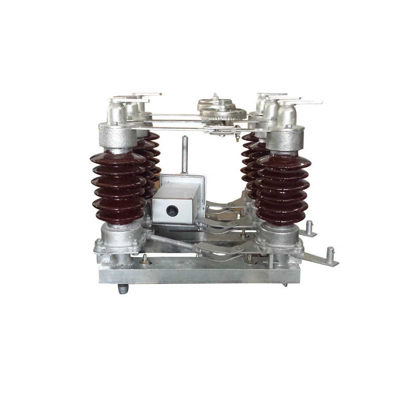
High Voltage Disconnect Switch Example
Indoor High Voltage Disconnect Switch
Structural type: plug-in and rotary.
(1) GN19-10 series plug-in indoor High Voltage Disconnect Switch
Three-phase common base frame structure, mainly composed of static contact, base, support insulator, pull rod insulator, and moving contact. The conductive part of the disconnector consists of moving and static contacts. The conductive part of each phase is fixed to the base through two support insulators, and the three phases are installed in parallel.
(2) GN30-10 type rotary indoor High Voltage Disconnect Switch
The switch body is fixed to the upper and lower surfaces of the switch base through two sets of insulators. The upper and lower surfaces are completely separated by a partition fixed on the switch frame. The switch is closed and opened by rotating the contact knife. Since the static contacts are installed on the upper and lower surfaces of the switch cabinet respectively, the live part and the non-live part are completely separated in the switch cabinet, thereby ensuring the safety of maintenance personnel. It is particularly suitable for installation in high-voltage switch cabinets.
5.2 Outdoor isolating switch
According to the number of support insulators, it can be divided into double-column, three-column and single-column types.
(1) GW4-110 type isolating switch
Double-column single-break horizontal rotary structure, mainly composed of base, insulating support, conductive part and operating mechanism, widely used in 10~110kV distribution equipment.
(2) GW5-110D isolating switch
The switch consists of base, rod-type support insulator, conductive knife, left and right contacts and transmission part, also known as V-type isolating switch. The isolating switch can be equipped with grounding knife according to needs, and is widely used in 35~110kV voltage level.
(3) GW11-252 type isolating switch
Double-column horizontal telescopic structure, the knife is horizontally telescopic, the opening and closing state is clear, and it is easy to inspect. The isolating switch is made into a single-pole form, and three single poles form a three-phase isolating switch. Main components: base, insulating support, transmission device, conductive knife, static contact and operating mechanism, etc.
(4) GW7-220 three-column disconnector
The GW7-220 type High Voltage Disconnect Switch adopts a three-column double-break horizontal rotary opening structure. It consists of a base, an insulating support, a conductive knife, a static contact, a transmission device and an operating mechanism.
(5) GW6-220GD single-column disconnector
Each pole of the GW6-220GD disconnector has two porcelain columns, namely a supporting porcelain column and an operating porcelain column. Since there is only one supporting porcelain column, it is called a single-column type. The static contact is fixed on the overhead hard busbar or suspended on the overhead soft busbar. The moving contact is fixed on the conductive folding frame.
(6) GW10-252 single-column disconnector
Single-column vertical telescopic outdoor AC High Voltage Disconnect Switch, including a base, an insulating support, a transmission device, a conductive knife, a static contact, an operating mechanism, etc.
6. Operating mechanism of disconnector
1. Manual operating mechanism
Lever type (disconnector with rated current less than 3000A)
Worm type (disconnector with rated current greater than 3000A)
2. Electric operating mechanism
7. Knowledge of disconnector use
1. Inspection and maintenance
Inspection during handover and acceptance: the operating mechanism, transmission device, auxiliary switching switch and locking device should be firmly installed, flexible and reliable in operation, and the position indication should be correct; the three-phase phase difference value should comply with the technical regulations of the product; the phase distance and the contact opening angle and distance when opening the switch should comply with the technical regulations of the product; the contacts should be in close contact; the paint should be complete, the phase color marking should be correct, and the grounding should be good.
2. Operation precautions
Inspect during operation: the insulator is intact, without cracks or discharge; the operating connecting rod and mechanical parts are not damaged or rusted, the parts are tight and in the correct position, without skew, looseness, falling off or other abnormal phenomena; the locking device is in good condition, and the pins and auxiliary contacts of the electromagnetic locking or mechanical locking of the disconnector should be in the correct position; the arc extinguishing angle of the blade and the knife mouth should not be burned, overheated, deformed, rusted, tilted, the contact contact should be good, the joints and contacts should not be overheated, and the temperature should not exceed 70℃; the blade and the knife mouth should not be dirty or burned, and the spring sheet, spring and copper braid should not be broken or broken; the grounding of the grounding switch should be good, especially the flexible parts that are easily damaged should be normal.
3. Maintenance
(1) Check the open and closed positions of the circuit breaker before operation to prevent the disconnector from operating under load;
(2) Close the circuit breaker manually quickly and decisively without excessive force;
(3) Pull open the disconnector quickly to extinguish the arc as soon as possible;
(4) If the disconnector is mistakenly closed under load, it is not allowed to be pulled open again;
If the disconnector is pulled wrongly, it should be closed immediately when the blade just leaves the fixed contact. If the disconnector blade has left the fixed contact, the mistaken disconnector must not be closed again.
(5) After closing the circuit breaker, check whether the contact is tight; after opening the circuit breaker, check whether each phase is in the disconnected position;
(6) After the operation is completed, lock the operating handle.

